How to fix the Kinetic F-16A MLU
tail housing shape problem
(so the decals would fit it)
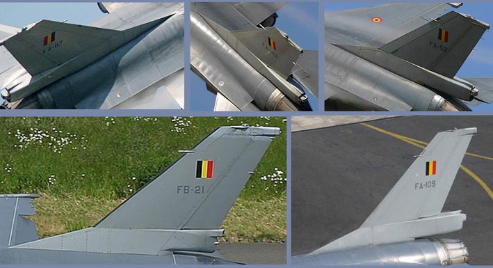
The F-16A/B tail base, which houses the ECM on the
Belgian F-16A and the parachute on the Dutch F-16A & F-16B
at the end part, is wrongly shaped in the new Kinetic 1/48 F-16A/B
kits, probably because they have based their dimensions on the
C/D tail base.
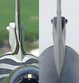
F-16A/B NATO base with until
the middle a smooth transition towards the tail:
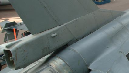
F-16C/D tail with thick base under
the tail:
On this page I'll try to explain how to fix this error
so my special tail decals will fit on this kits tail too.
Basicly the error in the design is the rectangular shape of the
interconnection areas of parts E1 / E2, E5 / E6 and C13 / C15,
which in real has a trapezium shape. The rectangular shape makes
these tails having a too thick step between the base and the actual
tail, as visible on the F-16C/D picture above. The connecting
areas of these parts should only be 5 mm at the top, while it
has now around 7 mm, reflecting in a 1 mm border below the tail
on each side.
How to fix it:
Step 1: Take each part and remove plastic on the inside
until you remain a tickness of 2.5 mm at the top, leaving the
bottom, the "leading edge" and the ECM/parachute house
from the middle (or E5/E6 at the end) as it is. So you'll make
a triangle in both horizontal and vertical directions,. You'll
notice the gap for the tail connection will disappear, so mark
& cut it out back again in the remaining pastic.
Step 2: Glue both left side parts together and the
right parts too, so not the left and right sides together as mentioned
in the instructions, making sure they are aligned nicely on the
outside. Put hem aside for an overnight, so the bondage is strong
enough for the next step.
Step 3: Glue both sides together, but only at the
leading edge, bottom and at the end - without any pressure to
get the gap together. Give it another overnight to make the parts
are glued together and can take some pressure.
Step 4: Force the gap together, making sure the transition
to the tail is smooth in the beginning part, as shown on the pictures.
Step 5: Place now the vertical tail., using the 1/48
drawing given on the back side of the instruction sheet as base,
as this part is also not 100% correctly angled... And as last
place part C23 (the extension above the rudder) some millimeters
more to the aft.
This should result in a better fix of the decal to
the tail.